A Simple Spectral Interrogation System for Optical Fiber Sensors †
by
 and
and
Paulo S. S. dos Santos
1,
Pedro A. S. Jorge
1,2,
José M. M. M. de Almeida
1,3 and
and
Luis Coelho
1,*
1
INESC TEC—Institute for Systems and Computer Engineering, Technology and Science, Engineering Faculty campus, University of Porto, 4200-465 Porto, Portugal
2
Department of Physics and Astronomy of Faculty of Sciences, University of Porto, 4169-007 Porto, Portugal
3
Department of Physics, School of Sciences and Technology, University of Trás-os-Montes e Alto Douro, 5001-801 Vila Real, Portugal
*
Author to whom correspondence should be addressed.
†
Presented at the 7th International Symposium on Sensor Science, Napoli, Italy, 9–11 May 2019.
Proceedings 2019, 15(1), 6; https://doi.org/10.3390/proceedings2019015006
Published: 5 July 2019
(This article belongs to the Proceedings of 7th International Symposium on Sensor Science)
Abstract
:Optical fiber sensors (OFS) based on long-period fiber gratings (LPFG) or on surface plasmon resonance (SPR) represent attractive solutions for detection systems in remote areas. An interrogation system consisting on wavelength modulation of fiber coupled distributed feedback (DFB) lasers was implemented and tested. The system uses a single photodetector to individually acquire the intensity of each DFB laser modulated by the OFS and the real transmission spectrum is reconstructed through curve fitting. Testing was accomplished by measuring the spectral features of an LPFG when changing the surrounding refractive index and errors lower than 1.8 nm in the 1530 to 1570 nm wavelength region were obtained.
1. Introduction
The application of long-period fiber grating (LPFG) or surface plasmon resonance (SPR) sensors for in-field sensing struggles on the development of cost-effective interrogation techniques. Although various systems have been used, most of them require the use of broadband light sources and optical spectrum analyzers, making the system bulky and expensive, therefore only suitable for laboratory environment use.
The internet of things (IoT) devices have been spreading at a fast pace, since the ratio of computer processing power versus price or form factor have been steadily increasing on the last decades [1]. On the other hand, the well matured state in optical fiber technology creates a great appeal for the creation of a low-cost device optical sensing unit. Several kinds of phenomena can be measured by LPFGs, with SPR devices or by using fiber Bragg gratings (FBG) [2,3,4].
2. Materials and Methods
The system here presented is a combination of distributed feedback (DFB) fiber lasers at different wavelengths with one fiber coupled photodetector and a sensing device.
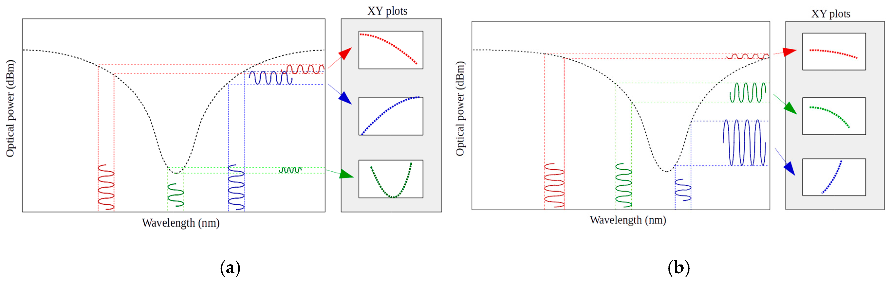
The operation mode of the interrogation technique is represented in Figure 1. In this scheme the light signals, that will pass through the sensor, are generated by three distributed feedback laser (DFB) with central emission wavelengths positioned at 1530, 1550 and 1570 nm, coupled together to a single output. Each laser is thermally modulated around their central wavelength at room temperature to around 4 nm span. This allows to gather the sensor modulated signal at each laser wavelength window by a single photodetector. The obtained data carries information about the intensity at each wavelength position, which is known by its linearity in wavelength shift with respect to temperature [5]. Crossing both information is possible to generate three XY plots for each DFB laser position. These plots carry information about the sensor optical power and peak position and slope. This information is then processed by curve fitting tools to reconstruct the original sensor shape.
When the dip is in positions between the lasers, the resolution is mainly limited by sensor asymmetries. Outside the spectral range defined by the used laser’s this technique is unreliable, since exists many curves that can be fitted to the gathered data.
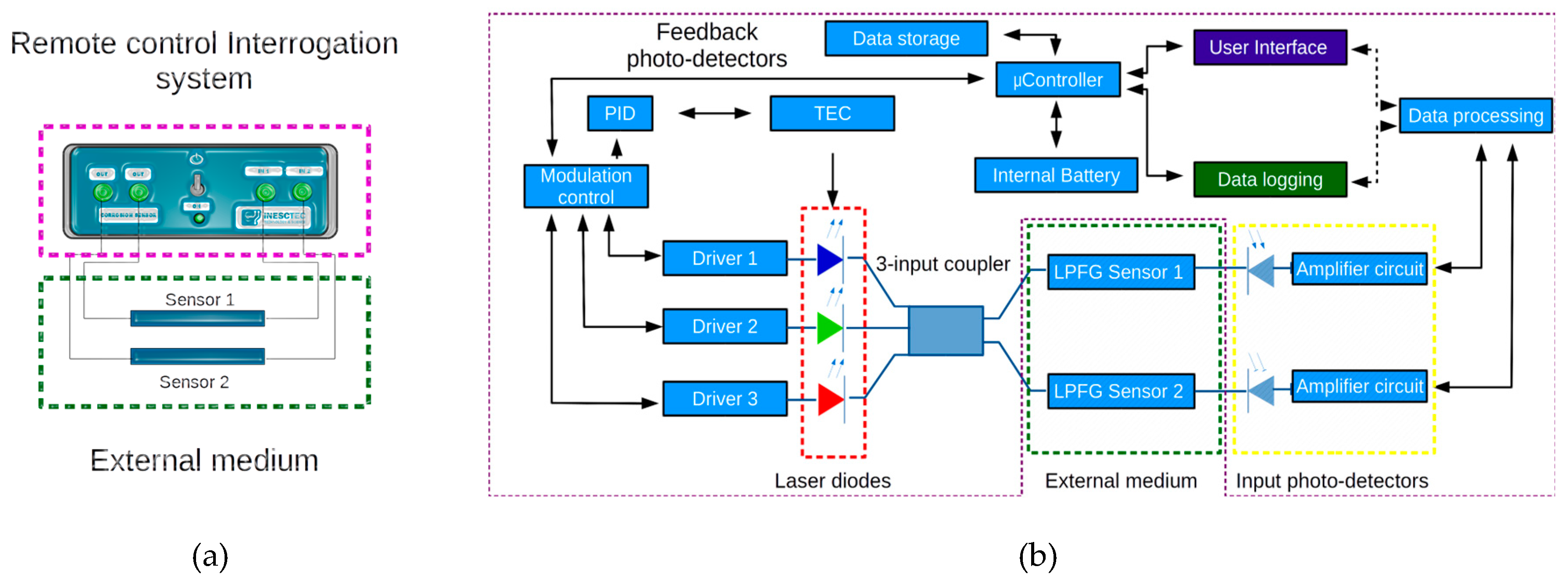
A workflow schematic of the built interrogation unit can be visualized in Figure 2a. The microcontroller is at the unit core, commanding the thermal modulation PID routine which will activate the Peltier as a heater or cooling device. The feedback photo-detectors are used to compensate optical fluctuations caused by thermal effects. The software routine sets the temperature of each laser, activates only one DFB at each moment and gathers the measured data by the input photodetectors and compensates the power with the feedback lasers for each photodetector. The unit can be used in laboratory by a user interface or as a data logger device. The built interrogation unit possess internal batteries and data storage.
The laser drivers can be of constant current type, or capable of providing current tuning mechanisms, where the produced wavelength shift has quasi-linear behavior [6]. So current modulation can be used as a fine-tuning mechanism. This way of controlling the DFB lasers present a way to interrogate three FBG located at the lasers window or be used in series with an LPFG sensor to provide a temperature or strain reference signal.
3. Results and Discussion
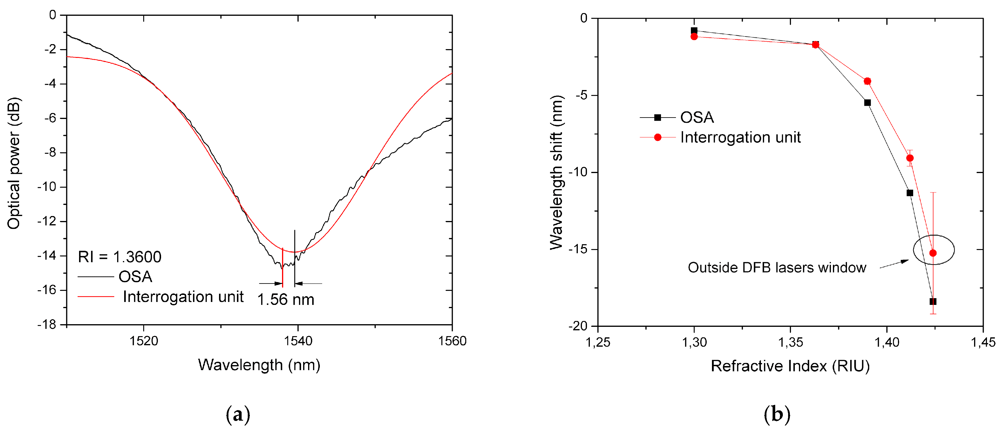
The validation of the interrogation scheme was obtained through with an LPFG sensor by changing the external refractive index, referenced from sodium D line, from 1.300 to 1.424. Results were made comparing the interrogation unit with the usual setup consisting of an OSA and a broadband light source. Figure 3a shows the comparison between the obtained fitting curve with the real spectra from the OSA with a refractive index of 1.3600. The estimated wavelength shift for the different external mediums is shown in Figure 3b and small deviation can be observed which can be justified by the asymmetry of the LPFG attenuation band.
The resolution of the OSA was set to 0.02 nm and presents the advantage of larger wavelength measurement range, limited by the broadband light source. The interrogation unit presents a greater measurement error when the dip of the sensor is lower than the first DFB laser at 1530 nm or higher than the last DFB laser at 1570 nm. Nevertheless, when the dip is located inside the lasers window an error less than 1.8 nm was obtained.
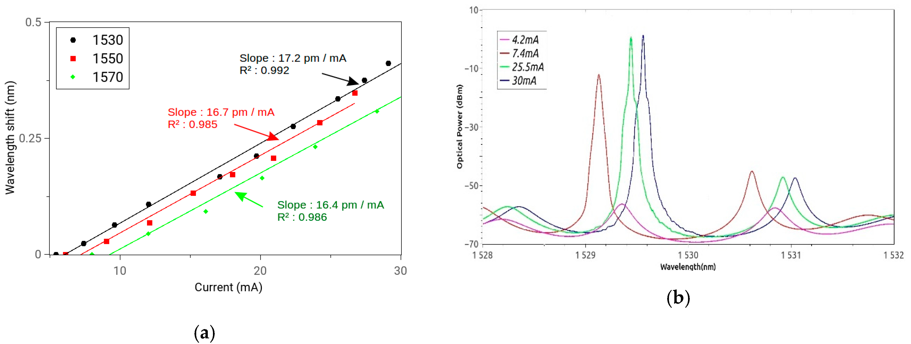
By checking the wavelength shift of each DFB laser with the current an almost linear behavior can be observed as illustrated in Figure 4a with a sensitivity of 17.2 pm/mA, 16.7 pm/mA and 16.4 pm/mA, for the 1530, 1550 and 1570 nm lasers, respectively. So current modulation can be used as a fine-tuning mechanism with a total range of around 300 pm, which suffice to scan the FBG. Represented on Figure 4b is the spectrum of the DFB lasers upon current modulation showing optical power variations. Interrogation of this unit can be made by several techniques, such as dithering by providing the DFB laser’s current modulation by a periodic waveform, or by simple scanning.
4. Conclusions
A portable and low-cost interrogation system with thermally modulated DFB lasers and a photodetector was developed to be applied on optical sensors with well-defined attenuation bands as gratings or plasmonic structures. The validation of the system was accomplished with a long period fiber grating with modifications in the surrounding medium to simulate the behavior of a chemical sensor and deviations better than 1.8 nm were obtained. Adding current modulation to the system a fine-tuning mechanism can be used with a total range of around 300 pm, allowing the implementation on hybrid sensors with fiber Bragg gratings.
Funding
This work has received funding by the project “SolSensors – Development of Advanced Fiber Optic Sensors for Monitoring the Durability of Concrete Structures”, with reference POCI-01-0145-FEDER-031220 supported by the Program Budget COMPETE - Operational Program Competitiveness and Internationalization - COMPETE 2020 and the Lisbon Regional Operational Program in its FEDER component and by the budget of FCT Foundation for Science and Technology, I.P.
Conflicts of Interest
The authors declare no conflict of interest.
References
- Parhana, P.; Lakshmaiah, M.V.; Allaudheen, S.; Dastagiri, S.; Saritha, V. Review on Internet of Things: Recent Applications and its Challenges. Int. J. Adv. Res. Electr. Electronics Instrum. Eng. 2017, 6. Available online: https://pdfs.semanticscholar.org/9a48/1dd7a59e0dfbd3b11044f16d17e789ed1106.pdf (accessed on 4 July 2019).
- Bhatia, V. Applications of long-period gratings to single and multi-parameter sensing. Opt. Express 1999, 4, 457–466. [Google Scholar] [CrossRef] [PubMed]
- Liang, M.-f.; Fang, X.-q.; Wu, G.; Xue, G.-z.; Li, H.-w. A fiber bragg grating pressure sensor with temperature compensation based on diaphragm-cantilever structure. Optik 2017, 145, 503–512. [Google Scholar] [CrossRef]
- Moayyed, H.; Leite, I.T.; Coelho, L.; Santos, J.L.; Viegas, D. Theoretical Study of Phase-Interrogated Surface Plasmon Resonance Based on Optical Fiber Sensors with Metallic and Oxide Layers. Plasmonics 2015, 10, 979–987. [Google Scholar] [CrossRef]
- Carter, J.; Snyder, D.; Reichenbaugh, J. Temperature dependence of optical wavelength shift as a validation technique for pulsed laser diode array thermal modeling. In Proceedings of the Ninteenth Annual IEEE Semiconductor Thermal Measurement and Management Symposium, San Jose, CA, USA, 11–13 March 2003. [Google Scholar]
- Hou, J.; Chen, X.; Wang, L.; Chen, W.; Zhu, N. A Method of Adjusting Wavelengths of Distributed Feedback Laser Arrays by Injection Current Tuning. IEEE Photonics J. 2012, 4, 2189–2195. [Google Scholar]
Figure 1.
Spectral representation of the interrogation technique where the input signal from the DFB lasers is thermally modulated. The obtained data can be cross referenced with the known wavelength response for the laser’s instantaneous temperature to form the XY plots with information about power intensity and wavelength position. (a) The sensor unit has its dip located at the central DFB; (b) The XY plots slope tendencies show that the dip is in closer proximity to the third DFB laser.

Figure 2.
Sensing scheme for the interrogation unit: (a) The developed interrogation unit presents two outputs and two inputs that can be used to perform parallel measurements; (b) The microcontroller device controls the thermal control for the DFB lasers, as well as their driving circuit, input photodetectors amplifier circuits to adjust their gain and make measurements. The unit can act as a data-logger or in laboratory when used with its graphical user interface.

Figure 3.
LPFG spectrum comparison between the developed interrogation unit and using a broadband light source and an OSA. (a) Comparison by the obtained fitting curve and the real spectrum measured by the OSA at 1.360 RIU; (b) Wavelength shift comparison for values of RI from 1.300 to 1.424.
Figure 3.
LPFG spectrum comparison between the developed interrogation unit and using a broadband light source and an OSA. (a) Comparison by the obtained fitting curve and the real spectrum measured by the OSA at 1.360 RIU; (b) Wavelength shift comparison for values of RI from 1.300 to 1.424.

Figure 4.
DFB lasers Current modulation (a) Current modulation results in a linear wavelength shift with a scope of around 300 pm; (b) spectrum of the lasers showing different optical power and wavelength shifts.
Figure 4.
DFB lasers Current modulation (a) Current modulation results in a linear wavelength shift with a scope of around 300 pm; (b) spectrum of the lasers showing different optical power and wavelength shifts.

Publisher’s Note: MDPI stays neutral with regard to jurisdictional claims in published maps and institutional affiliations. |
© 2019 by the authors. Licensee MDPI, Basel, Switzerland. This article is an open access article distributed under the terms and conditions of the Creative Commons Attribution (CC BY) license (https://creativecommons.org/licenses/by/4.0/).
Share and Cite
MDPI and ACS Style
Santos, P.S.S.d.; Jorge, P.A.S.; Almeida, J.M.M.M.d.; Coelho, L. A Simple Spectral Interrogation System for Optical Fiber Sensors. Proceedings 2019, 15, 6. https://doi.org/10.3390/proceedings2019015006
AMA Style
Santos PSSd, Jorge PAS, Almeida JMMMd, Coelho L. A Simple Spectral Interrogation System for Optical Fiber Sensors. Proceedings. 2019; 15(1):6. https://doi.org/10.3390/proceedings2019015006
Chicago/Turabian StyleSantos, Paulo S. S. dos, Pedro A. S. Jorge, José M. M. M. de Almeida, and Luis Coelho. 2019. "A Simple Spectral Interrogation System for Optical Fiber Sensors" Proceedings 15, no. 1: 6. https://doi.org/10.3390/proceedings2019015006